

Error Handling#
The error codes and related details are listed in here. When the error happens, you can follow the document of LSST M2 Controller ICD_revB (T14900-0124) for the possible action to fix the M2 system. For the simplicity, list the details in Troubleshooting. In some cases, you may need to restart the application in cRIO. You can follow the Restart Control System to do so. The log file in cRIO can support the debug as well. See Log File for the details. Sometimes, the errors are not real or easy to fix compared with the steps in Troubleshooting. There special cases are documented in Special cases.
Restart Control System#
There are two cRIO controllers (m2-crio-controller01.cp.lsst.org and m2-crio-controller02.cp.lsst.org) on the summit and one cRIO simulator (m2-crio-simulator.ls.lsst.org) in the base data center.
Before the restart of control system, check with the hardware engineers which cRIO is the right one to reboot.
All the IP addresses, accounts, and passwords are recorded in 1Passoword MainTel Vault.
You can log in the controller by ssh:
ssh ${account}@${ip}
Based on the OS platform, sometimes, you may need to do the following instead:
ssh -o "PubkeyAuthentication=no" ${account}@${ip}
After the login, you will be under the /home/admin directory.
The running command of control system is: {MainAppThread} ./lvrt, and you can use the top command to check it.
Usually, the related CPU usage is 5% at standby and 10-25% at running.
If the CPU usage is 50% or higher, that means there is the dead-lock happens in the application and you do need to restart the application.
To do so, you need to stop the running application first:
/etc/init.d/nilvrt stop
Wait for some time such as 3 minutes to make sure the application stops completely. Start the control system by the following command:
/etc/init.d/nilvrt start
This process will take around 3 minutes. A new log file will be generated, and you can see Log File for the details. It is noted that you will see 0% CPU usage of the application in the starting process for some time period. This is because the control system need 60 seconds to load the FPGA bit file at that period. After that, you should expect to see around 5% CPU usage of the application. If not, something is wrong and you can check the log file for the details.
Log File#
You need to log in the controller by following Restart Control System.
The log files are in the /u/log directory.
The name of log file is based on the time when the control system starts the running.
You can search the keyword such as error or others in the file by:
grep -nr "error" ${logFile}
If the application runs successfully, you should see something similar as the followings in the beginning of log file:
2023-08-31T07:12:02.789+00:00,DAQ process launched and should be running (paused state).
2023-08-31T07:12:02.885+00:00,Power control subsystem process launched and should be running (off state).
2023-08-31T07:12:02.957+00:00,Network interface process launched and should be running.
2023-08-31T07:12:03.035+00:00,TCP/IP interface process for GUI launched and should be running.
2023-08-31T07:12:46.540+00:00,M2 Controller has connected to the cRIO.
The log file will show the configuration files in use as something similar below as well:
2023-08-30T08:56:38.676+00:00,Load the system configuration file: /home/lvuser/natinst/config/sysconfig/Configurable_File_Description_20180831T092556_surrogate_handling.csv
2023-08-30T08:56:38.847+00:00,Load the cell mapping file: /home/lvuser/natinst/config/system/cell/cell-actuator_mapping_file.xml
2023-08-30T08:56:38.930+00:00,Load the home position file: /home/lvuser/natinst/config/home_position.xml
2023-08-30T08:56:39.013+00:00,Load the IMS file: /home/lvuser/natinst/config/dispIMS.json
As a reference, the /u directory has the softlinks with /home/lvuser/natinst directory as the following:
admin@NI-cRIO-9049-01EAEB52:/u# ls -al .
total 8
drwxr-xr-x    2 admin    administ      4096 Jun  7 06:54 ./
drwxr-xr-x   20 admin    administ      4096 Aug 31 07:10 ../
lrwxrwxrwx    1 admin    administ        28 Jun  7 06:53 config -> /home/lvuser/natinst/config//
lrwxrwxrwx    1 admin    administ        25 Jun  7 06:53 log -> /home/lvuser/natinst/log//
lrwxrwxrwx    1 admin    administ        28 Jun  7 06:54 script -> /home/lvuser/natinst/script//
Troubleshooting#
When the error happens, you can check the Troubleshooting Next Steps in the following table to fix the issue (based on T14900-0124). Sometimes, the alarms/warnings on GUI might be out-of-date, and you can try to reset them first (see Alarms/Warnings) before the further action. If you do not see the telemetry while connecting to the controller, you can try to restart the application (see the Restart Control System).
Code |
Failure |
Cause of Error |
Troubleshooting Next Steps |
|---|---|---|---|
6051 |
Actuator inner-loop controller (ILC) read error |
ILC responded with an exception code, did not respond at all (timeout), did not receive command, or reported fault status. |
Usually, this can be fixed by Code 6051 and 6088 or Code 6051 and 6052. Otherwise, most likely an ILC that is not responsive/failed. Look at the telemetry data to see which ILC address does not show a correct broadcast counter that increments by 16 every time step. That will narrow down the ILC to troubleshoot. If an ILC needs to be replaced, reference T14900-1002 ILC Programming Document to reprogram and configure the software properly. |
6052 |
Monitoring ILC read error |
ILC responded with an exception code or did not respond at all (timeout). |
The current firmware of the sensor ILCs generate this warning 4.5% of all samples. Updating to new firmware on the sensor ILCs should remedy this warning. For reference, updating firmware on the ILCs is described in T14900-1002 ILC Programming Document. Check the Code 6051 and 6052 as well. |
6053 |
cRIO communication error |
Loss of communication between the cRIO and M2 controller. |
Check to see if the power is lost to the cRIO. Check the internet connection between the switch and cRIO. Check there is the internet traffic jam or not. |
6054 |
ILC state transition error |
Internal ILC issue. ILC did not change state. |
Most likely an ILC that is not responsive/failed during startup. The log file will describe which addresses violates the state transition timing. Look at the first address which failed to meet timing. If it is determined that an ILC needs to be replaced, reference T14900-1002 ILC Programming Document to reprogram and configure the software properly. |
6055 |
Excessive force detected |
Measured force exceeded programmable threshold. |
Reference the constant.py to determine the force limits for the state when the excessive force was detected. Look at the Actuator Control or Detailed Force to determine the actuator(s) which violated the force limits. In Local mode, you can manually command the failed actuator(s) multiple steps slowly to lower its force below the closed-loop limit. You might need to do some small steps first to determine the step direction if you do not know. If the excessive force was originally detected in open-loop, click the Enable Open-Loop Max Limits button to provide force relief to unload the actuators. If for some reason it is determined that the load cell has been compromised and needs to be replaced, reference T14900-3024 Axial Actuator Replacemement. If this error is triggered from the rigid body movement, see the Recover the System from the Rigid Body Movement. |
6056 |
Actuator limit switch triggered [closed-loop] |
An actuator responded with a closed limit switch in any direction. |
Check to see on the Limit Switch Status which actuator(s) has triggered limit switches. Go into manual open-loop mode to drive the offending actuator(s) off the limits. If both the extend and retract limit switches indicate they have been closed, a communication error has occurred with that ILC and a power-cycle of system might be required. |
6057 |
Actuator limit switch triggered [open-loop] |
Same as error 6056. |
Same as error 6056. |
6058 |
Inclinometer error [fault] |
Communication error or the ILC reported fault. |
Check inclinometer sensor ILC for errors/disconnections. |
6059 |
Inclinometer error [warning] |
Same as error 6058. |
Same as error 6058. |
6060 |
Inclinometer difference error |
Excessive angular difference between the external and local inclinometers. |
Check to see if local inclinometer has come loose from cell. Ensure the external elevation is correct and calibrated. If necessary, reference T14900-0132 Inclinometer Calibration to recalibrate the local M2 inclinometer. |
6061 |
Motor power supply(s) over/under voltage [fault] |
Measured voltage exceeds programmable limits (2-sided). |
Using proper electrostatic discharge (ESD) protocols, inspect the motor power cables for any possible soft or hard shorts. |
6062 |
Motor power supply(s) over/under voltage [warning] |
Same as error 6061. |
Same as error 6061. |
6063 |
Comm power supply(s) over/under voltage [fault] |
Measured voltage exceeds programmable limits (2-sided). |
Using proper electrostatic discharge (ESD) protocols, inspect the communicaton power cables for any possible soft or hard shorts. |
6064 |
Comm power supply(s) over/under voltage [warning] |
Same as error 6063. |
Same as error 6063. |
6065 |
Excessive motor current |
Measured current exceeds programmable limit (1-sided). |
Run the actuator bump test and look at the telemetry to see if any one actuator is causing the motor bus current to spike when moving. That could indicate an issue in that actuator’s drivetrain and would need to be replaced. Using proper electrostatic discharge (ESD) protocols, inspect the motor power cables for any possible soft or hard shorts. Check the Code 6065 and 6066 as well. |
6066 |
Excessive comm current |
Same as error 6065. |
Same as error 6063. Check the Code 6065 and 6066 as well. |
6067 |
Power relay opening fault |
Power relay did not open when commanded by software. |
Some latency in the power relay opening is causing this fault. Could be caused by a faulty relay, a slowly changing condition could also be slowing down the opening of the relays. If necessary, the power relay opening threshold can be increased in software. |
6068 |
Power supply health fault |
Binary outputs signal power supply health fault. |
Binary signal that indicates the self-health monitoring within the power supplies have detected an issue. Repair or replace the offending power supply. |
6069 |
Multi-breaker trip on same comm power feed |
Breaker feedback showed two or more breaker trips. |
Same as error 6063. |
6070 |
Multi-breaker trip on same motor power feed |
Same as error 6069. |
Same as error 6061. |
6071 |
Single breaker trip |
Breaker feedback showed single breaker trip. |
Same as errors 6061 and 6063. |
6072 |
Power supply load sharing error |
Based on binary output from redundancy module. |
Could be caused by a bad power supply redundancy module or an actual mismatch in power supply load sharing. If the power supplies are not contributing equal loading, it may also be possible that the power supply health fault could be seen (error 6068). In either case, try replacing the redundancy module or using different power supplies. |
6073 |
cRIO 50 msec cycle time monitor [fault] |
Measured loop time exceeded 50 ms for three consecutive cycles. |
Look for additional processes that could be costing computation time on the cRIO. |
6074 |
cRIO 50 msec cycle time monitor [Warning] |
Measured loop time exceeded 50 ms for one cycle. |
Look for additional processes that could be costing computation time on the cRIO. |
6075 |
Excessive cell temperature differential |
Intake-exhaust temperature diff exceeds programmable threshold. |
Look at the Diagnostics to see what the intake/exhaust temperatures are reading. Reference the Configuration View to see what the temperature threshold is set to. Ensure threshold is set reasonably. Increase threshold if necessary. Otherwise, look for blockage in the exhaust path of the cell assembly. |
6077 |
Configurable parameter file read error |
The software cannot properly read in the file or something is corrupted with the data read from the file. |
Check the |
6078 |
Displacement sensor out of range |
Sensor value out of range. |
Most likely a failure of the displacement sensor. Look in the Utility View to determine which displacement sensor is out of range. First inspect the sensor ILC associated with the offending displacement sensor. Ensure wiring is correct. Manually move the failed displacement sensor while monitoring the Utility View to determine if any valid readings are received. If not, it could be necessary to replace the displacement sensor or the sensor ILC. |
6079 |
Inclinometer out of range |
Same as error 6078. |
Unlikely failure to happen. If an inclinometer sensor ILC had trouble commmunicating, the inclinometer warning/fault would be tripped. This fault is designed to ensure the inclination value received is within range. |
6080 |
Mirror temperature sensor out of range [fault] |
Same as error 6078. |
Most likely a failure of the temperature sensor. Look in the Utility View to determine which mirror temperature sensor is out of range. First inspect the sensor ILC associated with the out of range sensor. Since the mirror temperature sensors are bonded to the mirror, alternative methods for replacing that signal must be explored. |
6082 |
Airflow temperature sensor out of range |
Same as error 6078. |
Most likely a failure of the temperature sensor. Look in the Utility View to determine which airflow temperature sensor is out of range. On the cell, inspect that offending airflow temperature sensor and replace if necessary. |
6083 |
Axial actuator encoder out of range |
Same as error 6078. |
Most likely a failure of the encoder sensor. Look in the Detailed Force to find the offending axial actuator. Inspect the wiring of the encoder of that actuator as well as the actuator ILC to ensure proper connects. |
6084 |
Tangent actuator encoder out of range |
Same as error 6078. |
Most likely a failure of the encoder sensor. Look in the Detailed Force to find the offending tangent actuator. Inspect the wiring of the encoder of that actuator as well as the actuator ILC to ensure proper connects. |
6088 |
Tangent load cell fault |
Tangent load cell calculations violate any of the monitoring conditions. |
Possible causes: tangent actuator ILC, tangent actuator load cell, tangent actuator ILC wiring, bad inclination signal. If it is determined that a tangent actuator is to be replaced, reference T14900-3025 Tangent Actuator Replacement. If an ILC needs to be replaced, reference T14900-1002 ILC Programming Document. Check the Code 6051 and 6088 as well. If this error is triggered from the rigid body movement, see the Recover the System from the Rigid Body Movement. |
Special cases#
The special cases of error handling are listed below.
Connection Timeout#
If you have the connection timeout, you can try to ping the controller first by:
ping ${ip}
The next step is to check the commandable SAL component (CSC) has the connection with the controller or not. Before the fix of DM-37422, you can only have one client (GUI or CSC) to the controller. If the CPU usage of application has 50% or higher, this will block the connection and you can follow Restart Control System to fix it.
In addition, if there is no enough disk space in controller, it will block the connection as well.
Although there is the crontab job in controller to clean the log files regularly, it would be worthful for you to check the files and related sizes in the /u/log directory in controller.
If none of above is the reason, you could always try to restart the application as the final solution.
Code 6051 and 6088#
This often comes about when there is an inconsistency in elevation angle and the last loop-up table (LUT) calculation. For example if you move the mirror/TMA in elevation while the M2 is off/standby or not in closed-loop (force-balance) control.
First check that two error codes might not be real and you could try the followings first:
Restart the control system (see Restart Control System).
Power-cycle the whole M2 system (see Power-Cycle).
More likely, when you try to transition to the Enabled state or closed-loop control, you will get the error codes of 6051 or 6088 immediately. When this happens, you just need to move the M2/TMA back to the original elevation angle (when it was last in closed-loop), and you should be able to enable the system again. If you forget the original elevation angle, you may need to check the engineering facility database (EFD), try-and-error, or calculate the possible elevation angle based on the measured forces at that moment.
Code 6051 and 6052#
These two error codes might not be real and you could try the followings first:
Power-cycle the M2 system by following Power-Cycle.
Make sure the control system is running by following Restart Control System and Log File.
Release the interlock signal by following Reset the M2 Interlock Signal.
Code 6065 and 6066#
These two error codes might not be real because the related judgement in controller is based on the power thresholds in the configuration file:
24V Accuracy Warning
24V Accuracy Fault
Current Threshold
The first step to debug is to check the thresholds in configuration make sense or not. If they are, you may need to check the power supplies in hardware.
The power to the motors and ILCs (for telemetry) goes from the cabinet to the M2 cell using 3 cables. The 78 actuators are grouped by 3 cables (or zones) and every cable powers the motors and ILCs to 26 actuators. If the error was Excessive Comm Current (code 6066), this means the telemetry was consuming more than expected. If one actuator was failing, it would imply the overcurrent would be seen on only one cable. Therefore, if you test one cable (or zone) at one time, you should be able to identify which group of actuators might have the power issue. But if the error kept the same for all 3 zones, it would imply a failure in every one of 3 zones, which was highly unlikely to be the case, and you might need to check something else that might result in these errors.
Recover the System from the Rigid Body Movement#
The available range of rigid body momement is restricted to the assembly and it would induce the error codes: 6055 and 6088 if the movement is big. Actually, in the normal telescope survey, the M2 should stay at the origin with the minimum stress. However, in some cases, we would need to adjust the mirror’s position and this might trigger the error to transition the system to leave the closed-loop control to protect the mirror.
If the error code is 6055, you can check the Detailed Force to see which actuator has the force higher than the threshold of closed-loop control. Usually, the axial actuator is related to the z-direction and the tangent link is related to the x- and y-direction. Once the actuator is identified, you can move it in steps to have the force lower than the threshold of closed-loop control, and then, put the system into the closed-loop control to recover the system. It is noted that the single actuator movement will increase the stress of the system. Therefore, the actuator’s force should not differ from the threshold too much before transitioning to the closed-loop control. Otherwise, the system might be damaged from the high stress (see the Diagnostics for the 4 fault conditions of tangent load cell).
If the error code is 6088, it might be easier to bypass this error code and move the related tangent link to decrease the tangent force error. First, you need restart the application to clear the internal history (see Restart Control System). Second, bypass the error codes at Alarms/Warnings. Move the tangent link under the open-loop control to let the tangent force error to be less than the thresholds. Then, transition to the closed-loop control if possible. Finally, reset the enabled faults mask to the default value to protect the system.
But sometimes, it might be difficult to calculate the needed actuator movement.
Therefore, you could change the following threshold of tangent force error in /u/config/parameter.json in controller: tangentLink_totalWeightError, tangentLink_loadBearingLink, tangentLink_thetaZmoment, or tangentLink_nonLoadBearingLink (to log in the controller, see Restart Control System).
Restart the control system to read the updated configuration file, and transition the system to the closed-loop control to minimize the stress.
Finally, change the thresholds to the original ones and restart the applicaiton to use the default values.
But the action to bypass the error code or change the thresholds might break the system totally. Therefore, it would be better to check with the maintainers first before the above actions.
Power-Cycle#
If the M2 is on the TMA, you might need to use the internet interface of general power distribution unit (PDU) to power-cycle it. Before the power-cycle, you should check with the hardware or system engineers first. The internet interface of PDU is tea_pdu and the related credential is in 1Passoword MainTel Vault. You can only reach this interface when you are under the control network, and the VPN can not reach it directly. You can power off followed by powering on the M2 cabinet (wait >30 seconds in between) in the following widget:
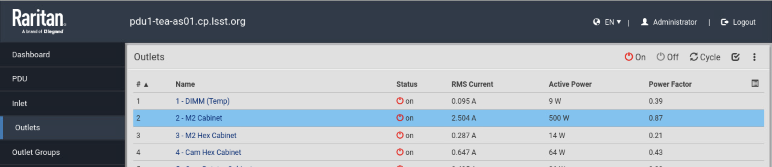
Power-cycle the M2 on the general PDU.#
Otherwise, if the M2 is on the level 3, it should be straigt-forward to unplug and replug the power cable (wait >30 seconds in between).
After rebooting the M2, you need to wait for 5 minutes or more before the connection request. If you do not want to wait long, you can follow the Restart Control System to make sure the control system is running and waiting for the TCP/IP connection.
Reset the M2 Interlock Signal#
To reset the M2 interlock signal, if the M2 is on the TMA, you might need to push the RESET blue button of the M2 ACTUATOR tab on the global interlock system (GIS) cabinet at the level 2 as the following:
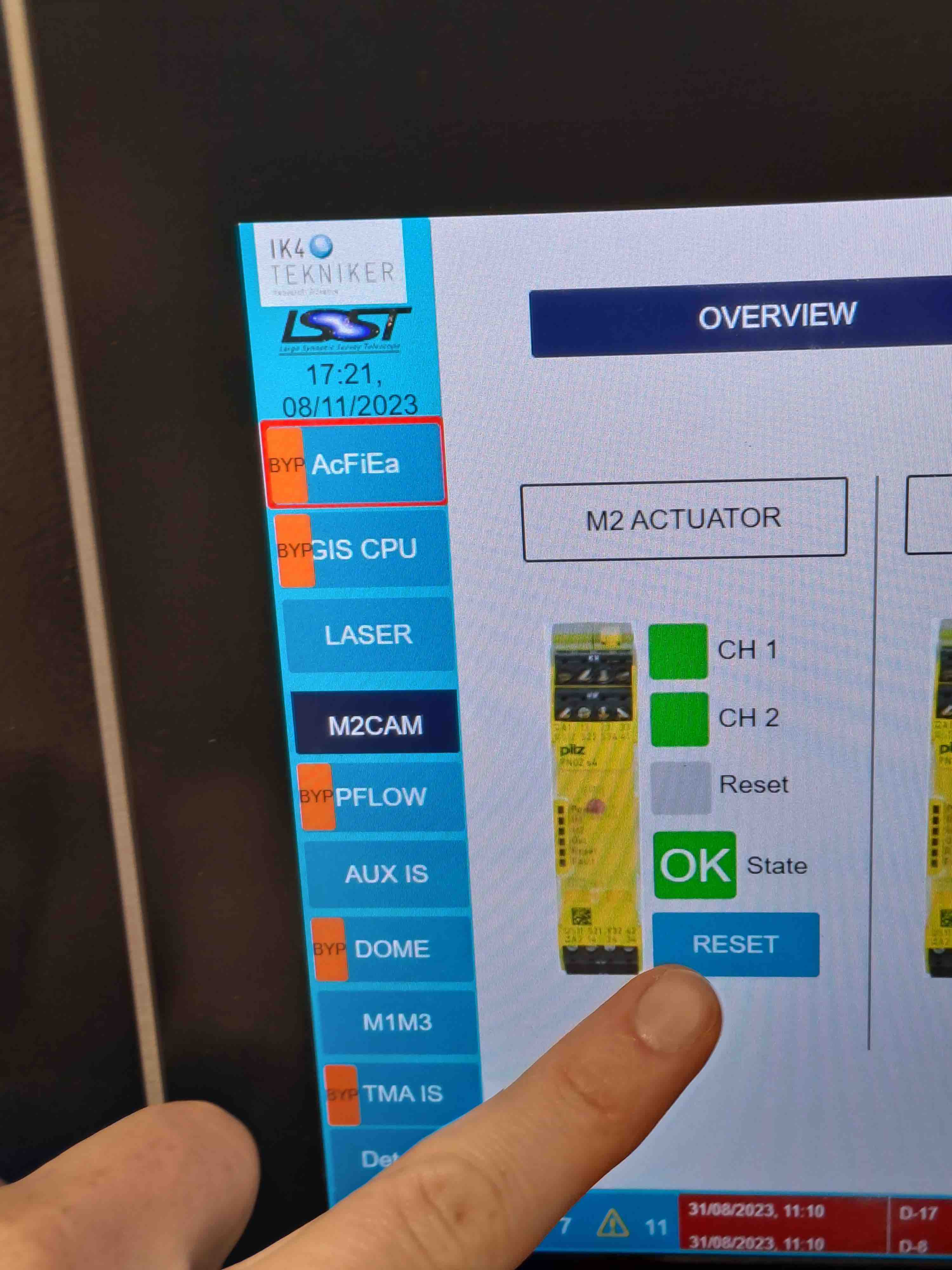
Reset the M2 GIS.#
After having pressed the RESET button, wait 2 minutes before restoring the system with the M2 Python GUI.
Otherwise, if the M2 is on the level 3, usually, press and release the e-stop button would be enough.